Carding Machine Specification – spinning machine


Latest posts by Tanima Rahman Tanni (see all)
- Spinning Carding Machine : Chute Feed System - April 3, 2015
- Carding Definition - April 2, 2015
- Carding Machine Specification – spinning machine - February 3, 2015
Spinning Machine – Carding Machine Specification :
SPECIFICATION OF CARDING MACHINE:
working width: 1000-1020 mm
taker-in diameter: 250-350 mm, RPM: 500-1300
cylinder diameter: 1016-1290 mm, RPM: 200-800
doffer diameter: 500-700 mm, RPM: 30-100
no of flats: 100-112
no of flats in working position: 37-43
direction of flat run: forward/backward
can size: (920mm*1200mm)-(1000mm*1220mm)
no of sliver produced: 1
sliver fineness: 0.1-0.2 Ne
power required: 5.5-12.5 Kw
air required: 1500-300 Nm3h
can changer: automatic
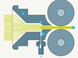
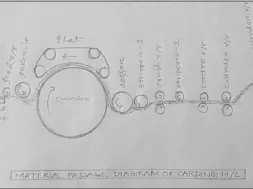
MATERIAL PASSAGE DIAGRAM OF CARDING M/C:
<image >
OPERATING PRINCIPLE OF CARDING M/C:
1. pipe ducting 10. flats
2. feed chute 11. cleaning unit
3. transport roller 12. fixed carding bars
4. feed arrangement 13. cover plates/grid
5. taker-in/licker-in 14. doffer
6. grid equipment 15. stripping device
7. suction duct 16. Calendar roller
8. main cylinder 17. cans
9. fixed carding bars 18. Coiler
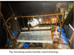
In modern installations, raw material is supplied via pipe ducting into the feed chute.
A transport roller forwards the material to the feed arrangement. Feed arrangement consists of a feed roller and a feeder plate. These roller and plate push the sheet of fiber slowly into the operating range of the licker-in. Side by side, they maintain optimal clamping.
The materials are opened into tufts by the licker-in. Tufts are passed over grid equipment and transferred to the main cylinder.During the movement through mote knives, grids, carding segments etc the material loses the majority of its impurities. Suction duct carries away the waste.
The tufts go to the main cylinder and open up into individual fibers between the cylinder and the flats, which is called the actual carding process. The flat comprises of 80-116 individual carding bars combined into a belt moving on an endless path. Nowadays 80-116 (in modern cards about 27) of the flats are located in the carding position; the rest are on the return run. During this return, a cleaning unit eliminates fibers, neps and foreign matter from the bars.
Fixed carding bars are designed to assist the carding machine operation. Grids/cover plates enclose the underside of the main cylinder. After carding, the main cylinder carries along the fibers that are loose and lie parallel without hooks. They does not remain in transportable form. That is why doffer is required. The doffer combines the fibers into a web. This is possible because doffer has substantially lower peripheral speed relative to the main cylinder. A stripping device draws the web from the doffer. After calendar rollers have compressed the sliver to some extent, the coiler deposits it in cans. The working rollers, cylinder and flats are provided with clothing, which becomes worn during fiber processing, and these parts must be reground at regular intervals.
FEED SYSTEM of CARDING M/C:
There are two types of feeding to the cards:
1. lap feed system
2. chute/flock feed system
LAP FEED SYSTEM:
The system of feeding material to the card in the form of scutcher laps is called the lap feed system.
ADVANTAGES OF LAP FEED SYSTEM:
1. maintenance of lap thickness is easier
2. installation is very flexible
3. can be operated with several blends
4. the blends can be allocated to individual carding machines
5. auto-leveler is not required
6. investment and maintenance cost is lower
DISADVANTAGES OF LAP FEED SYSTEM:
1. more manpower is needed in transport and lap change.
2. additional burden on the taker-in as scutcher laps are happily compressed.
3. lap run out causes fault at the time of replacement by a newer one.
4. clean and good fiber wastage takes place during lap change.
5. higher production is not possible.
(5530)
Latest posts by Tanima Rahman Tanni (see all)
- Spinning Carding Machine : Chute Feed System - April 3, 2015
- Carding Definition - April 2, 2015
- Carding Machine Specification – spinning machine - February 3, 2015