Air Jet Spinning


MD. MAZBAH UDDIN
Latest posts by MD. MAZBAH UDDIN (see all)
- Different Types of Sewing Thread - December 5, 2017
- Air Jet Spinning - December 3, 2017
- Spin Finishes , Sizes and Grease - December 3, 2017
Air Jet Spinning
Air Jet Spun Yarn
1 . The air-jet spun yarn is fascinated yarn consisting of a core of parallel fibers held together by wrapper fibers.
2 . The structure of air-jet spun yarn is essentially that of comparatively straight central core of fibers held together by taut surface fibers wound onto the central core helically.
3 . The straight fibers are termed as “core fibers” while the taut, helically fibers called as “wrapper fibers“.
Classes of Air-Jet Spun Yarn :
The fascinated yarn structure was classified into three (3) distinct classes as below:
Class 1 :
In this structure, a part of yarn that has regular helical wrapping and the yarn core is crimped. The crimpiness is due to the buckling force generated by wrapping fiber torque and tension. The angle of wrap varies between 40 to 45 degree.
Class 2 :
This structure has twist less core, randomly wrapped by fibers, in singular state and group with angle of wrap varies between 45 to 90 degree.
Class 3 :
This structure consists of unwrapped section of yarn core, at time having residual twist. The yarn structure resembles that of ring yarn with very low twist in fibers.
False Twisting
Ⅰ . Yarn manufacture using the air jet primarily produces fascinated yarns using the false twist principle. Hence, we discuss about the principle of false twisting before going into actual air jet spinning.
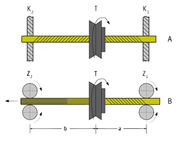
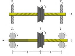
Ⅱ . Figure 1 demonstrates the principle of operation of false twisting. If a fiber strand A is held firmly at two spaced points by clamps K1 and K2 and is twisted somewhere between them, this strand always takes up the same number of turns of twist before and after the twist element (T). However, these turns have opposing directions of twist, which are represented in the example in Figure 1A as Z-twist on the right and S-twist on the left.
Figure 1 : Principle of False Twisting
Ⅲ . If the clamps are replaced by rotating cylinders (Z1 and Z2 in Figure 1B) and the yarn is allowed to pass through the cylinders while twist is being imparted, the result is governed by the false-twist law and is different from the case of the stationary yarns, as previously assumed. A moving yarn entering the section (b) already has turns of twist imparted in section (a). In the example illustrated (B), there are turns of Z twist.
Ⅳ . As the twist element is generating turns of S twist in the left hand section, this simply means that each turn of the Z twist imparted in the first section (a) is canceled by a turn of S twist imparted in the second section (b). The fiber strand thus never has any twist between the twisting element and the delivery cylinder.
In a false-twist assembly, turns of twist are present only between the feed cylinders and the twisting element. This principle is exploited, for instance, in false-twist texturing.
Fascinated Yarn through False Twisting
Ⅰ . The idealized structure of the fascinated yarn, as shown in Figure 2 consists of parallel fibres held together by wrapper fibres. The wrapper and core fibres are composed of same staple fiber material. Since there is no real twist in the core, this type of yarn structures facilitate high production rates.
Ⅱ . The fibres upstream of the false twister have twist which gets cancelled with opposite twist once it passes the false twister leading to no twist downstream of the false twister. If there are enough edge fibres in the feed fibrous assembly, then these edge fibres do not get twisted with the core fibres upstream of the false twister.
Ⅲ . Hence, as the core fibres get untwisted after the false twister, these wrappers which had no twist earlier, get wrapped around the core fibres. This produces fascinated yarn structure. These types of yarn structures were first promoted by DuPont. Figure 4 shows the schematic of the DuPont system which did not get commercial success. 
Figure 2: Idealized Structure of Fascinated Yarn
The principle involved in the production of fascinated yarn using the false twisting method.

Figure 3 :production of fascinated yarn using the false twisting method
Two nozzle air-jet spinning ( Murata MJS System )
Ⅰ . Figure 5 shows a schematic of a Murata MJS double nozzle air jet spinning system. The feed material is a draw frame sliver fed from a can (1) which is passed to a drafting arrangement (2), where it is attenuated by a draft in the range of 100 – 200. The fiber strand delivered then proceeds to two air jets (3 and 4) arranged directly after the drafting arrangement. The second jet (4) is the actual false-twist element.
Ⅱ . The air vortex generated in this jet, with an angular velocity of more than 2 million rpm, twists the strand as it passes through so that the strand rotates along a screw-thread path in the jet, achieving rotation speeds of about 250 000 rpm. The compressed air reaches the speed of sound when entering the central canal of the false-twist element. Since the axial forces are very low during this rotation, only low tensions arise in the yarn.
Ⅲ . The ability of the vortex to impart torque is so high that the turns of twist in the yarn run back to the drafting arrangement. The fiber strand is therefore accelerated practically to full rotation speed as soon as it leaves the front roller. The edge fibers which ultimately bind the yarn together by becoming wrapping fibers are in a minority. For process reasons, they do not exceed about 5% of the total yarn mass.
Ⅳ . These edge fibers exhibit relatively few turns of twist in the same direction as the false-twisted core fibers or can even be slightly twisted in the opposite direction. This is partly ensured by causing the strand to emerge from the nip line in a broadly spread form, but mainly by generating in the first jet (3) a vortex with an opposite direction of rotation to the vortex in the second jet (4).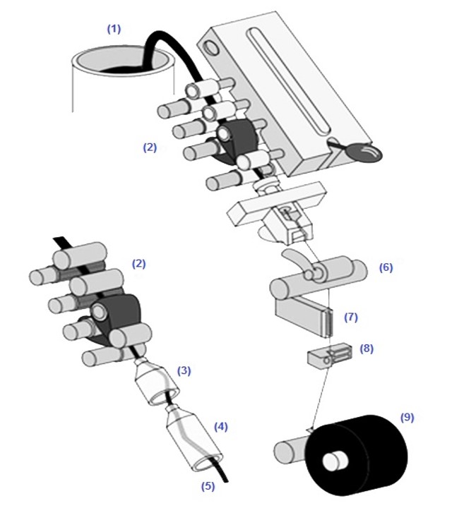
Ⅴ. This first vortex is in fact weaker in intensity than the second and cannot really affect the core fibers, but can grasp the edge fibers projecting from the strand at one end. Since the first vortex acts against the twist direction generated by the second jet, it prevents the edge fibers from being twisted into the core or even twists them in the opposite direction around the core fibers. As the strand runs through the second jet, the following occurs:
Ⅵ . The turns of twist generated by the jet (3) are canceled in accordance with the false-twist law. The core fibers, i.e. the vast majority, no longer exhibit any twist; these fibers are arranged in parallel. On the other hand, the edge fibers (which previously exhibited no twist, relatively little twist, or even twist in the opposite direction) receive twist in the direction imparted by the jet (4); they are therefore wound around the parallel fiber strand. They bind the body of fibers together and ensure coherence.
Ⅶ . The resulting bundled staple-fiber yarn passes from the take-off rollers (6 in Figure 5) through a yarn-suction device (7) and an electronic yarn clearer (8) before being wound onto a cross-wound package (9).
A twist diagram prepared by Dr. H. Stalder demonstrates this twisting procedure (see Figure 6)
Yarn Strength
1 . The tenacity of the fascinated yarns spun with air jet depend on the yarn count. The coarser yarns are weaker than the finer yarns for the same fiber type. Contrary to the expectation, yarns produced with finer fibres show lower tenacity compared to the yarns produced with coarser fibres.
2 . The reason for the above observations is that the strength of the fascinated yarns is derived from the amount of wrapper fibres and the intensity of wrapping. The edge fibres are the ones which ultimately get converted into wrapper fibres. The number of edge fibres are limited to the surface of the yarn and are independent of the number of fibres in the core as shown in Figure 7.
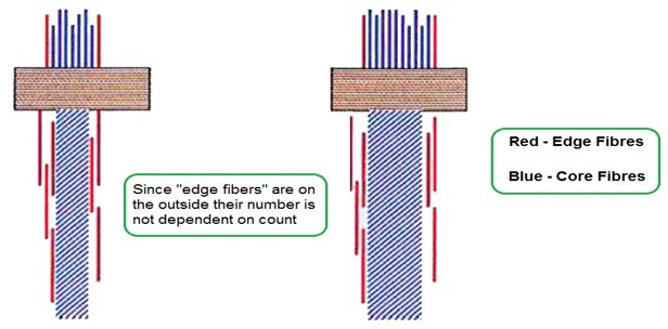

Figure 7: Disposition of Edge fibers in Fascinated Yarn
3 . In case of finer fibres, the number of core fibres increase but the edge fibres remain constant. This leads to reduction in the proportion of edge fibres, which in turn reduces the lateral stress brought in by the wrapper fibres. This results in decrease in yarn strength.
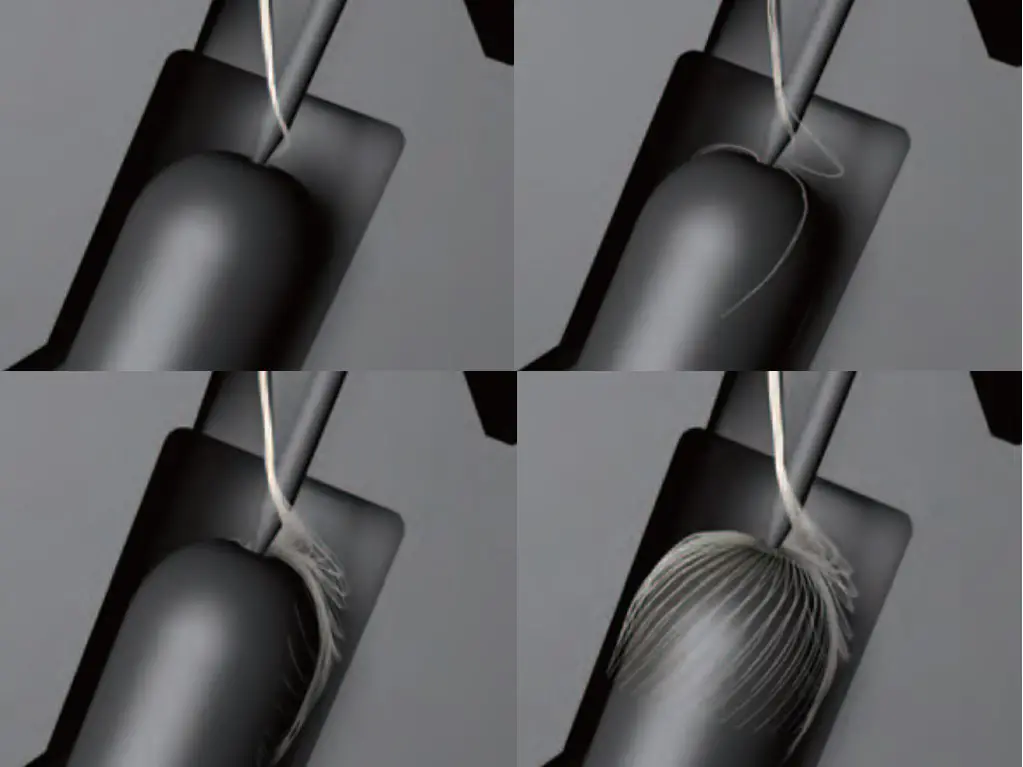
4 . Again in case of coarser yarns, in addition to having lesser proportion of wrapper fibres, the intensity of wrapping also less as shown in Figure 8 as compared to finer yarns.
Two nozzle air-jet spinning: Raw materials requirements
The process has so far been restricted spinning :
1 . Pure synthetic fibers,
2 . Blends of synthetic fibers or
3 . Blends of synthetic with cotton fibers.
4 . Pure cotton can be processed only in combed form and usually still gives a low strength product. (50-70% ring spun)
5 . Dirt in the fiber material acts as a disturbing factor.
6 . Almost all the yarn characteristics are improved by the use of longer and finer fibers.
7 . About 80 fibers at least are needed in the yarn cross-section.
The fiber should have :
1 . Higher strength.
2 . Fairly high fiber-to-fiber friction.
3 . Low bending stiffness.
4 . Low resistance to twist; and
5 . Only a small proportion of short fibers.
Yarn Characteristics
The yarn character is slightly different from that of ring spun yarn. It is somewhat:
1 . Weaker
2 . Stiffer and
3 . Harder
The hardness can be reduced by using finer fibers and by treatment of the finished product with a softener (e.g. with a silicone).
Additional points of comparison with ring-spun yarn are :
Positive :
1 . Good evenness (like ring-spun yarn).
2 . Good abrasion resistance.
3 . Low tendency to pilling.
4 . Low snarling tendency.
5 . Shrinkage similar to that of ring-spun yarn.
Negative :
1 . Higher resistance to bending.
2 . Slightly lower covering power.
3 . Wrapping fibers not uniformly distributed over the length; sometimes there are slightly more on the surface, sometimes slightly fewer.
Specification of MJS machine
| 1 | Spinning positions | per machine up to 72 (single sided) |
| 2 | Delivery speed | 150 – 300 m /min |
| 3 | Raw materials | synthetic fibers and blends. |
| 4 | Count range | 20 – 80 Ne |
| 5 | Feedstock type | draw frame sliver |
| 6 | Type of yarn | bundled single yarns |
| 7 | Yarn characteristics | Reasonable strength, low hairiness, rough outer surface |
| 8 | Field of use | Ladies outerwear, shirting material, sheets. |
Principle of Yarn Formation in Murata Vortex Spinning
1 . In MVS spinning, a finisher sliver (fibers) is supplied directly to the drafting device. The drafted fibers are passed through the air jet nozzle and hollow spindle to make them into a yarn strand. The process is described below:
2 . The fibers coming out of the front rollers are sucked into the spiral orifice at the entrance of the air jet nozzle, and they are then held together more firmly as they move towards the tip of the needle protruding from that orifice.
3 . At this stage , the fibers are twisted from the force of the air jet stream. This twist motion tends to flow upwards. The needle protruding from the orifice prevents this upward propagation (twist penetration). Therefore, the upper portions of some fibers are separated from the nip point between the front rollers, but they are kept “open”.
4 . After the fibers have passed through the orifice, the upper portions of the fibers begin to expand due to the whirling force of the jet air stream and they twine over the hollow spindle. The fibers twined over the spindle are whirled around the fiber core and made into MVS yarn as they are drawn into the hollow spindle. The finished yarn is wound onto package after the its defects have been removed.
Principle of yarn formation in MVS
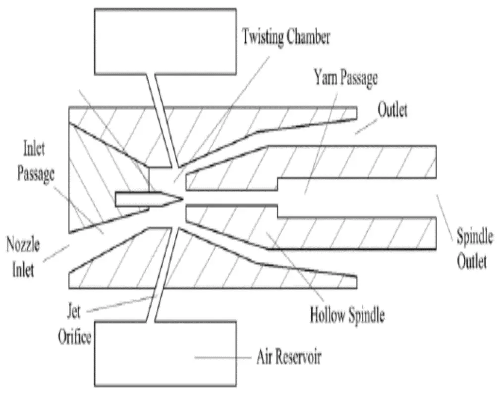
Figure : Vortex Spinning apparatus and Yarn formation zone
Factors of the MVS
1 . The distance between the front roller nip point and the tip of the spindle (indicated by “L” I n the above figure) affects the physical characteristics of MVS yarn greatly.
2 . The larger this distance, the more the “upper-portion open” fibers, resulting in a yarn closer to real-twist yarn in characteristics.
3 . However , if the distance is too large, the waste fiber rate will also be extremely large.
4 . Therefore, in general, the distance should be slightly shorter than the average length of the fibers that will be supplied.
Fiber properties for different spinning System
| Order of importance | Ring | Rotor ( open -end ) | Air jet | Friction |
| 1 | Length and length uniformity | Strength | Fineness | Friction |
| 2 | Strength | Fineness | Cleaniness | Strength |
| 3 | Fineness | Length and length uniformity | strength | Fineness |
| 4 | Cleaniness | Length and length uniformity | Length and length uniformity | |
| 5 | Cleaniness |
Table : order of importance of Fiber properties for different spinning System
Why Airjet not suitable for coarser count
1 . The number of edge fibres are limited to the surface of the yarn and are independent of the number of fibres in the core.
2 . If we select finer fiber, the no. of fibers in yarn cross-section will be more. These can easily be wrapped by the edge fibers.
3 . If we select coarser fibers, no. of fibers in yarn cross section will be less. These can also be wrapped easily .
4 . Hence whether we choose fine or coarser fiber the wrapping doesn’t decrease. So it is beneficial to select coarser fibers.
Economics of Airjet
1 . Manpower : Due to automation and the elimination of the roving frame and the winder, the operation of a Air-jet spinning mill requires considerably less manpower.
2 . Space : Air-jet spinning mills require considerably less floor space compared to ring spinning mills. The space requirement is typically around 50 % of that of a conventional mill.
3 . Energy: A large part of the energy needed for Air-jet spinning is used, for generating compressed air. On the other hand, the much smaller premises allow for a reduction in the energy required for the air conditioning plant. In addition, the energy required for mechanical drives is comparatively low. In total therefore, the energy requirement in Air-jet spinning is thus quite considerably lower than in ring spinning.
4 . Waste : The higher fiber loss in Air-jet spinning inevitably results in correspondingly higher waste costs.
5 . Market impact : Air-jet spinning is a very young spinning system. Nevertheless, up to mid-2004 about 32 000 Air-jet spinning positions (equivalent to approximately 600 000 ring spindles) have been delivered worldwide. These machines are installed in more than 15 countries, including Europe.
(4672)
MD. MAZBAH UDDIN
Latest posts by MD. MAZBAH UDDIN (see all)
- Different Types of Sewing Thread - December 5, 2017
- Air Jet Spinning - December 3, 2017
- Spin Finishes , Sizes and Grease - December 3, 2017