Different Action of Combing Machine

Trishna Mondal Etu
Latest posts by Trishna Mondal Etu (see all)
- Lap Preparation in Combing | Sliver Lap Machine | Ribbon Lap Machine - July 13, 2018
- Basic Concept of Combing Process | Types of Comber Machine - July 13, 2018
- Different Action of Combing Machine - July 13, 2018
Part 1: Basic Concept of Combing Process | Types of Comber Machine
Part 2: Lap Preparation | Sliver Lap Machine | Ribbon Lap Machine
Part 3: Production Calculation of Lap Former Machine
Part 5: Production Calculation of Comber Machine
Different Action of Combing Machine | Material Passage Diagram of Comber
Operational Sequence of Comber Machine:
1 . Feeding: Lap is feed into the machine between the feed roller and feed plate. The feed rollers move and materials passes forward.
2 . Nipping and Combing by cylinder Comb: The nippers moves forward so that the fibers are clamped between them. At this time the cylinder comb is ready to comb.
3 . Piecing: Nippers are open again and move backward. Detaching rollers give backward rotation. In case of forward movement of nippers, the projecting fibers are placed upon the return piecing.
4 . Delivery and combing by top comb: The detecting rollers rotate to begin for delivering the sliver. At this time, top comb is active and combs the sliver.
Actions of Comber:
1. Feeding
2. Nipping
3. Combing by cylinder Comb
4. Piecing
5. Delivery and combing by Top Comb
6. Doubling
7. Drafting
8. Calendaring
9. Coiling
10. Doffing
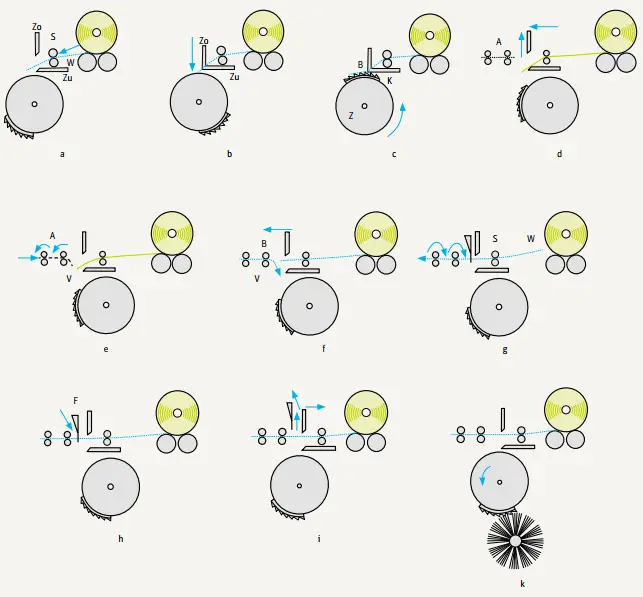
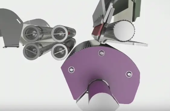
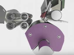
Fig: Sequence of operations
(a) Feed rollers (S) move lap sheet (W) forward by a small amount (4.3 – 6.7 mm), while nippers (Zo/Zu) are held open (feed).
(b) Upper nipper plate Zo is lowered onto cushion plate (Zu) so that the fibers are clamped between them (nipping).
(c) Combing segment (K), mounted on rotating cylinder (Z), sweeps saw-teeth through fiber fringe (B) and carries away anything not held by the nippers (rotary combing).
(d) The nippers open again and move toward detaching rollers (A) (nippers forward).
(e) Meanwhile detaching rollers (A) have returned part of the previously drawn-off stock (web V) by means of a (partial) reverse rotation, so that the web protrudes from the back of the detaching device (web return).
(f) In the course of the forward movement of the nippers the projecting fiber fringe (B) is placed on the returned web (V) (piecing).
(g) The detaching rollers begin to rotate in the forward direction again and draw the clamped fibers out of web (W) held fast by feed rollers (S) (inside the nippers) (detaching).
(h) Before the start of the detaching operation, top comb (F) has thrust its single row of teeth into the fiber fringe. As the fibers are pulled through the teeth of the top comb during detaching, the trailing part of the fringe is combed, thus making up for the inability of the circular combs to reach this part of the fringe (passive combing by the top comb).
(i) As the nipper assembly is retracted, the nippers open for the next feeding step. The top comb is withdrawn. A new combing cycle begins.
(k) Contrary to the movements of the other parts, the combing cylinder rotates continuously. During this rotation and at a certain instant the combing segment is brought into the vicinity of a rapidly revolving brush mounted below the combing cylinder. This brush removes the imperfections, etc., from the combing segment, and ejects them into an extractor that carries the noil away to a collecting filter system.
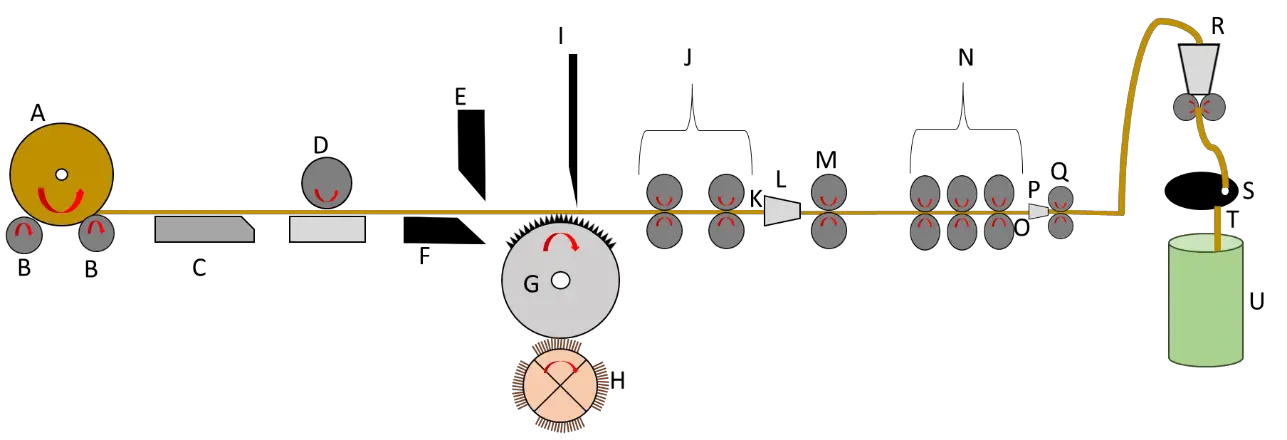
Material Passage Diagram of Comber:
A= Mini Lap H= Cylinder brush O = Wave
B= 1st feed roller I = Top comb P = Trumpet
– nipper open, forward most position
– Detaching roller forward rotation
–Forward feeding (opening)
–Backward feeding (closing)
– Detaching roller backward rotation
A = Mini Lap H = Cylinder Brush O = Wave
B = 1st feed roller I = top Comb P = Trumpet
C = Feed Plate J = Detaching Roller Q = Calendar Roller
D = 2nd feed roller K = Wave R = Coiler Roller
E = Top Nipper L = Condenser S = Coiler plate
F = Bottom nipper M = Delivery Roller T = Combed
G = Cylinder Comb N = Drafting Zone U = Sliver
Index Wheel:
In comber outside the cylinder shaft, a wheel is attached with 40 equal parts names as Index wheels. There is a pointer on it to indicate the index number. Various motion of comber m/c and its timing such as nippers, cylinder, top comb, roller and different setting and adjustments are done by different index number. With the reference of index number, Nipper comb, cylinder and conjugative position, motion and adjustment limit are selected
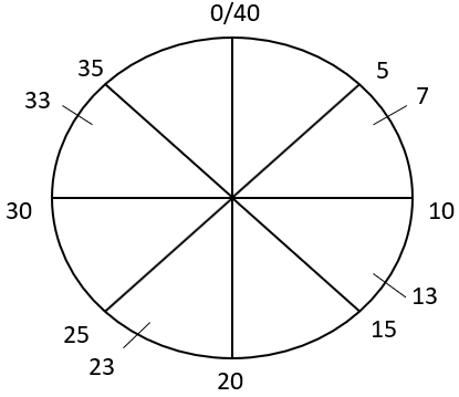
Pointer position 33 to7:
Combing by cylinder comb
Nippers closed and at backward most position
Pointer position 17 to 23:
Delivery and combing by top comb
Delivery, combing by top comb
Nipper open, forward most position
Detaching roller forward rotation
Pointer position at 7 to 17:
Forward feeding (opening)
Pointer position 23 to 33:
Backward feeding (closing)
Pointer Position 13 to 17:
Detaching roller backward rotation
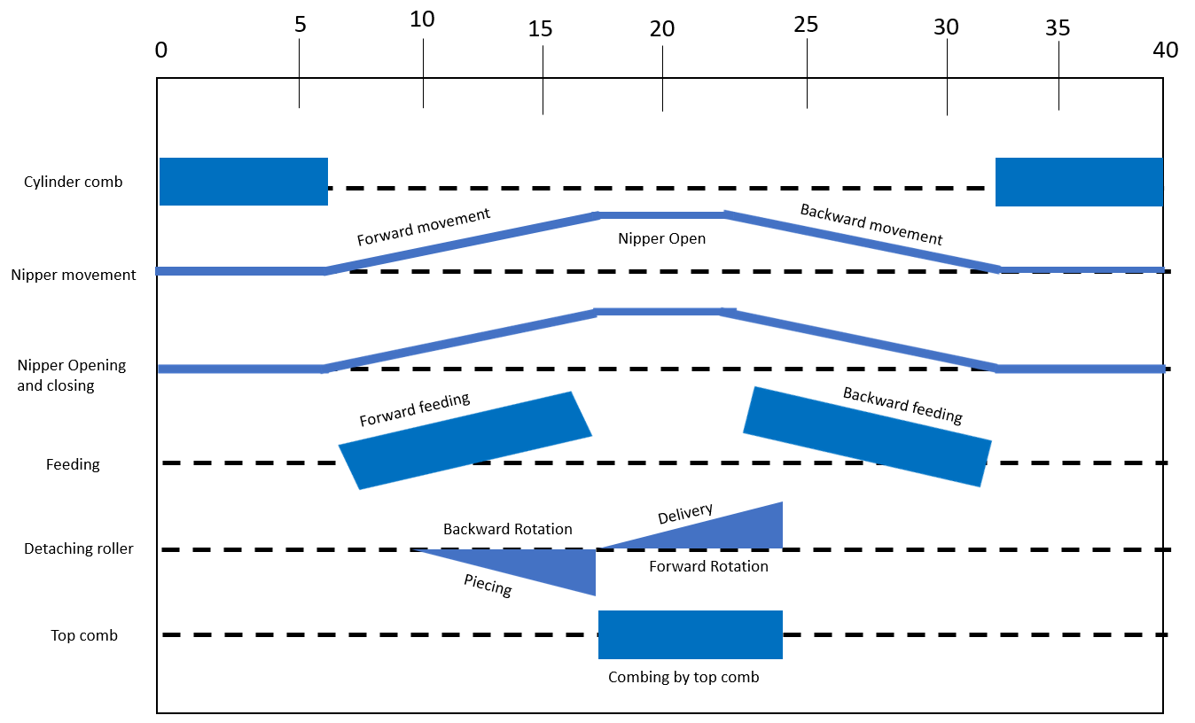
Diagram of Movement:
Diagram of movement is the logical explanation of index wheel in two-dimensional medium
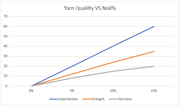
Comber Waste:
The waste material (short fibers) removed during combing is referred to as noil (or sometimes as comber waste). Noil consists of shorter fibers and neps. The amount of noil removed in the combing process may be varied to suit the circumstances and is usually expressed in percentage based on the original weight of laps fed into the machine. The percentage of noil being calculated as follows:
![]()
Semi-combing = 5-10% noil.
Normal combing = 10-20% noil.
Super combing = above 20% noil.
Methods of Improving Noil Percentage:
By changing the type of feed. Backward feed will obviously result in increasing no percentage because during backward feed of fibres combing is done 4 times where as it is 3 times in case of forward feed.
By changing the ratchet wheel number i.e. decreasing the ratchet wheel teeth amount of noil % can be increased.
By changing the distance between nipper to detaching or by changing the index. If the index is more, then the % of noils removed will also be more.
By decreasing the distance between top comb and unicomb the percentage removal of noil is increased.
Degree of Combing:
The amount of Noil (Noil= Short fibers+neps+impurities) extracted during combing expressed in percentage is called degree of combing. Degree of combing depends on the end use of yarn.
Types of combing on the basis of degree of combing:
| Types | % of Noil |
| Half combing | Noil% upto 8% |
| Ordinary combing | Noil% upto 9-15% |
| Full combing | Noil% 16-18% |
| double combing | Noil% 19-25% |
Combing Efficiency
Combing efficiency is calculated based on the improvement in 50% span length, expressed as a percentage over 50% span length of the lap fed to the comber multiplied with waste percentage:
![]()
where,
S is the 50% span length of comber sliver
L is the 50% span length of comber lap
W is the waste percentage
Effects of Change of Settings on Sliver Quality:
Effect of comber setting on noil extraction:
- Effect of detachment setting: The distance between the leading edge of the feed plate and the nip of the detaching roller close setting for the same staple length will reduce the noil exrtraction% and vice versa.when the setting is wider for the particular type.
- Effect of top comb setting: The amount of waste extracted can also be adjusted by alternating the position of top comb, combing operation will be proper and the noil extraction will be high. If it is set closer to the nippers, the waste extraction will be lower.
Factors influence the comber setting:
1. If the distance between the feed plate and detaching roller is higher then the staple length of fiber will increase
2. If the distance between top comb and detaching roller is less then the noil extraction % will increase.
3. If noil material feed rate increase then the production rate.
4 If the production quality and noil extraction % is higher then the production rate will be decreased.
Part 1: Basic Concept of Combing Process | Types of Comber Machine
Part 2: Lap Preparation | Sliver Lap Machine | Ribbon Lap Machine
Part 3: Production Calculation of Lap Former Machine
Part 5: Production Calculation of Comber Machine
(5057)
Trishna Mondal Etu
Latest posts by Trishna Mondal Etu (see all)
- Lap Preparation in Combing | Sliver Lap Machine | Ribbon Lap Machine - July 13, 2018
- Basic Concept of Combing Process | Types of Comber Machine - July 13, 2018
- Different Action of Combing Machine - July 13, 2018