Effect Of Sliver Handling On Quality Of Sliver And Yarn
A Technical Seminar On Effect Of Sliver Handling On Quality Of Sliver And Yarn
CHAPTER 1
INTRODUCTION
The ultimate aim of the every spinning unit wants to produce 100% even yarn. But still today it is not possible to producing a uniform yarn. Because there are some factors which will influence the quality of the yarn. One of the important factor is method of sliver handling. A well-known fact is “Carding is a heart of spinning”. Due to the more innovation in the carding machines, almost all the machine parameters and process parameters should be optimized. So the carding machine can able to delivering good quality of sliver. Nowadays “Sliver handling is the heart of spinning”. Because the challenge is how to handle the sliver without affecting the quality. So the better yarn demands better sliver and obviously the better sliver demands correct sliver handling system.
Cans are ideal packaging container which is used in pre spinning department for storing and transporting the material to subsequent machines. During the transportation, it must provide smooth handling with higher degree of protection. The effect of poor sliver handling may not be noticeable in preparatory stage, but it is much noticeable and magnified while drafted over speed frame and ring frame. Every component of the sliver can will be purposefully designed, because each component of the machine will affect the quality of the sliver and hence the quality of the yarn. It causes a both random variation in sliver and periodic variation in yarn. So the selection of can for particular type of fibre or sliver is much important.
So In this report, I have reported that the influence of sliver handling on the quality of sliver and yarn. Then the advancement in the sliver handling can for obtaining the best quality of yarn.
CHAPTER 2
SLIVER CAN ACCESSORIES
2.1 TOP RIM AND BAND
The top rim and band holds the shape of the sliver cans, preventing the cans from developing cracks and collapsing when rotating under high speed. These are made up of both stainless steel or galvanized steel.
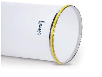
Figure 1 Top Rim and Band
2.2 BOTTOM RIM AND PLATE
It gives the greater support to the sliver cans. Then the bottom rim holds the shape of the can. The bottom plates are made from Galvanized Irons (GI) and the Rims are made on heavy duty presses with special ribs contours for additional strength and life.
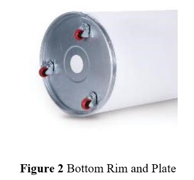
2.3 TOP COVERS
The sliver coils are laying on the top plate. Moulded PPCP (Poly propylene copolymer) top covers are used with an anti-slippage surface to give a proper grip and surface without rupturing the sliver. ABS (Acrylonitrile butadiene styrene) option is also available to give more strength and durability to top covers.
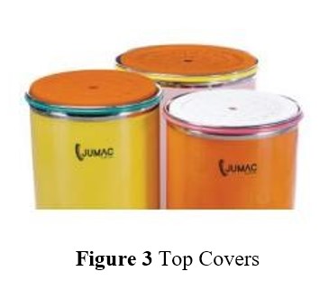
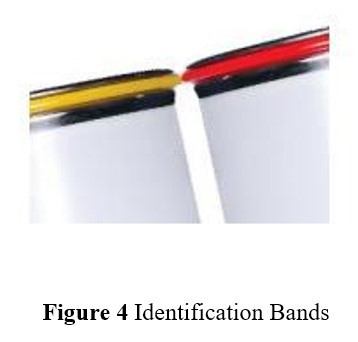
2.4 IDENTIFICATION BANDS
PVC based bands act as shock absorber during bumping of cans and also helps to differentiate the sliver counts during production. An attractive range of colors act as an excellent value addition for spinning cans.
2.5 SPRINGS
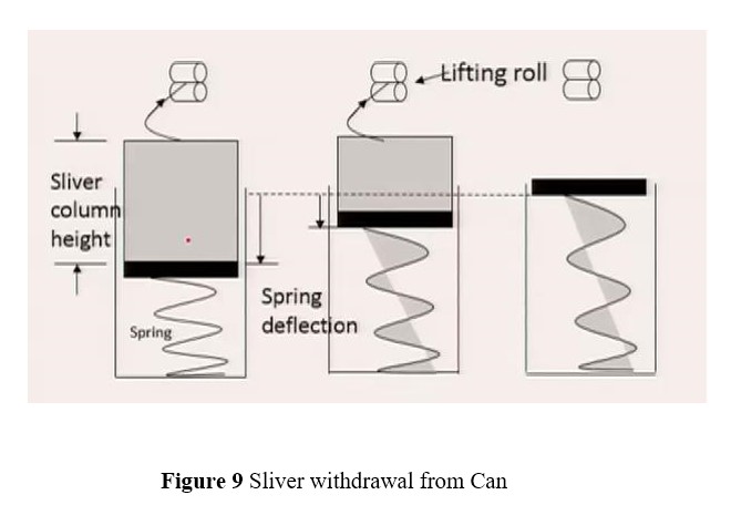
Springs are the heart of the sliver can. This will ensure that the distance between the top layer of sliver and feed roller to be constant. Typically there are two types of spring used in the sliver can.
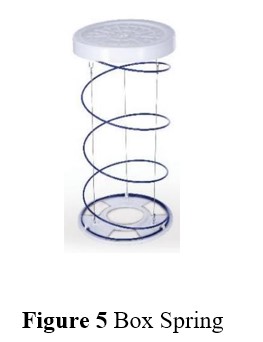
2.5.1 BOX SPRING
Anti-rust and heat treated, These springs are made from high carbon steel wire that enables uniform load and movement during operations. Every single spring is individually calibrated to give longer and consistent life. A minimum initial is advisable for maintaining the desired sliver height especially in open end and rotor spinning.
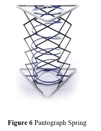
2.5.2 PANTOGRAPH SPRING
Electro-welded galvanized shutters in criss-cross shape ensure uniform spring movement and maintain constant sliver height. For sizes upto 24 inches plastic moulded covers and from 28 to 48 inches, Galvanized covers are used for zero tilting and proper balance of the sliver. A spring hardened and tempered with care to retain the original sliver properties as desired by the spinning master.
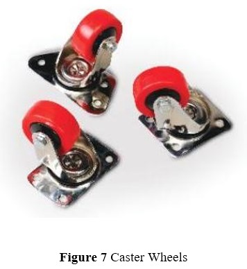
2.6 CASTER WHEELS
The casters are placed under bottom plates and it is used to transport the can from one place to another place. The caster wheels must have high tensile strength, abrasion resistance and heat stability. A complete range of casters for spinning cans with a fluff-free design is available to provide smooth sliver handling on the floor.
High pressed zinc coated body also ensures longer life. Wheel options in both PP (polypropylene) and nylon 6 are available in the market.
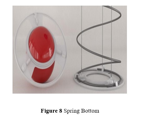
2.7 SPRING BOTTOM
It is manufactured from molded polypropylene. It is used for hold the spring firmly and does not damage the can while inserting or remove the spring.
CHAPTER 3
INFLUENCE OF CAN ACCESSORIES ON SLIVER QUALITY
3.1 EFFECT OF TOP RIM AND BAND
The top rim and band are holds the shape of the sliver can. In the modern draw frame the cans are rotating under very high speed. It leads to collapse the structure of the sliver can. So the top rim and band ensure that it firmly hold on the can.
3.2 EFFECT OF BOTTOM RIM AND PLATE
The bottom rim and plate will give the greater support to the can. It also contribute to hold the shape of the can during rotating under high speed. So if the bottom plate is not properly attached, the can will collapse and loss of sliver.
3.3 EFFECT OF TOP COVERS
The top surface of top covers must be anti-slippage in nature. When the sliver coils are laid on the top covers the coils should not sliding to each other. So that nowadays the top covers are manufactured with grooves for holding the coils in their place. Also the top covers must have smooth surface. Because when the coils withdrawn from the can it should be easily come out without any damage. If the top surface of the cover will rough it will results in fibre loss. These fibres may be accumulate in the machine parts and restrict the movement of can. The top covers are placed on the spring. The bottom surface of top covers should have adequate grip towards the spring. Otherwise the top cover may tilt and loss of sliver.
3.4 EFFECT OF IDENTIFICATION BAND
Identification bands are used as a shock absorbing material in the can. It prevents the collapsing of shape of the can during bumping of can. Also it is used for differentiating sliver hank. Otherwise two different count may be mixed together will results in quality variation.
3.5 EFFECT OF SPRING
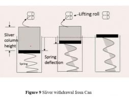
The springs are helps to maintain constant height between top layer of sliver coils and lifting roller. When the can is empty, there is no spring deflection and the plate stands close to the rim of the can.

As the sliver withdrawn, the pressure on the spring progressively reduces. The spring at the bottom expands and the can plate moves up with the column of sliver on it. The top layer of sliver column also moves up by an similar amount and thus it always stay close to the lifting roller. This is required to avoid sliver breakage or stretch due to its own weight.
3.5.1 INFLUENCE OF FIBRE DENSITY
For a given spring constant, the deformation of the spring depends upon how much weight is acting on it. As long as weight on it remains same irrespective of fibre or sliver type, the compression will be same. However, for the same weight of sliver column height will be more for voluminous fibre (polyester and acrylic) and more for carded sliver in comparison to drawn or combed sliver. While filling the can with voluminous fibre a stiffer spring will be beneficial as it will create more pressure on the sliver column. This will helps to compress the voluminous, resilient sliver and pack it well within can. If same spring (as used for cotton) is used, the deformation on the polyester sliver column will be less causing column height to increase.
3.5.2 LIMITATIONS OF BOX SPRING
The box spring is ideally suitable for smaller diameter cans or it is suitable for over centre coiling mechanism. Because in the under centre coiling, the sliver coil diameter is less than the radius of the can. So during coiling the spring may not give much stability to the top cover. If it is a under centre coiling, the diameter of the coil is more than the radius of the can. So the top cover has much higher stability in smaller diameter cans in under centre coiling.
3.5.3 ADVANTAGES OF PANTOGRAPH SPRING
Pantograph springs are versatile springs which is used for wide range of diameter of cans. The pantograph springs are manufactured by electro-welded galvanized shutters that take up an even crisscrossed shape. It is moulded with top cover which result in zero tilting and huge stability while filling with sliver.
3.6 EFFECT OF CASTER WHEELS
In the spinning unit, one of the uncontrollable thing is generation of fly waste. The fly waste may accumulate in the machine parts or simply fall on the ground. So during the caster wheel movement, the fly fibres may stick on the surface of the caster wheels. It leads to restriction of can movement and sliver may fall on the ground. Also the caster wheels are subjected to high load while transporting. So that the caster wheels must have higher tensile strength, abrasion resistance and heat stability. Since the casters are made up of nylon 6 (Thermo plastic material) it should have excellent heat stability. The rigid type of castors are not preferable in the industry because of its linear movement (it can be move either in the forward direction or backward direction). But in case of swivel castors it is movable in all the direction. So the swivel castors are very feasible for industries.
3.7 EFFECT OF SPRING BOTTOM
It must hold the spring firmly otherwise it may affect the performance of spring.
To ensure that during changing the spring, it should not damage the body of the can.
CHAPTER 4
SELECTION OF CAN
4.1 TYPES OF CAN
There are two types of can which is supplied by the manufacturers. Those are
- Cylindrical can
- Rectangular can
4.2 SUITABILITY OF CYLINDRICAL CAN
Cylindrical cans are widely used in the preparatory machines. Because the springs are incorporated in the cans for maintaining sliver column close to the lifting roller. The combed slivers are very sensitive to stretching. The stretching in the creel will results in periodic mass variation in yarn. Cylindrical cans are available with a wide range of diameter and height. The cylindrical cans are used in delivery part of carding, draw frame, comber machines. But the limitation of cylindrical can is it occupies much larger space when compared to rectangular can.
4.3 SUITABILITY OF RECTANGULAR CAN
The rectangular sliver cans are mostly preferable for rotor spinning machines or open end spinning machines. The rectangular cans have several advantages over the cylindrical cans.
- Capacity is increased by about 75%, due not only the geometry of the can but also the elimination of the can spring.
- It permits optimal utilization of the space available down-stream processing.
- It is suitable for automation.
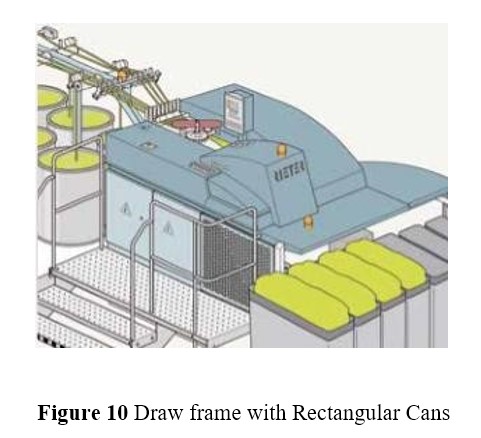
For the rotor spinning, carded sliver is a feed material. The carded sliver has innumerable fibre shapes when compared to other slivers. So when we the small amount of stretch given to the sliver, the energy will be stored in the sliver. When we remove the stress, suddenly the sliver is come back to its original shape. Even the rectangular cans don’t have a spring, it is suitable for rotor spinning machine. Because the carded sliver is less prone to stretching in nature.
CHAPTER 5
ADVANCES IN SLIVER HANDLING
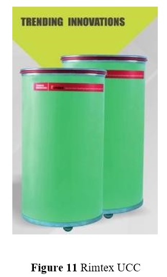
5.1 SINGLE CAN FOR MULTIPLE SLIVER HANDLING
Incorrect sliver handling can damages the sliver. The yarn made from it, has many more imperfections. So the better yarn demands better sliver. The better sliver demands correct sliver handling. Rimtex (Leading manufacturer of sliver can) introducing for first time single can used for multiple type of sliver handling. It is called as UTILITY COMBINATION CAN (UCC). The single can used for carded, combed and synthetic sliver handling.
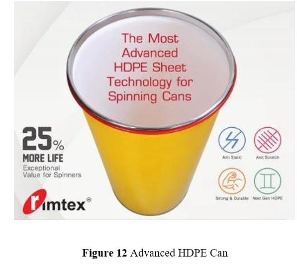
5.2 ADVANCED HDPE SHEET TECHNOLOGY
This technology is also introduced by Rimtex. The features of the spinning can is to be listed as follow.
- It has a moulded HDPE sheet and the surface should be very smooth. So there is reduction in static and reduction in sliver migration.
- It is strong and durable. So it has 25% more life than the conventional can.
- The surface of the inner side of the can has to be anti-scratch.
CHAPTER 6
LITERATURE REVIEW
6.1 SLIVER CAN SPRING
Sliver can spring is considered as heart of the sliver can, which is subjected to fatigue loading, So with time spring stiffness reduces. Most of the spinning industries in developing countries including India are extensively using older sliver cans having low spring stiffness than normal, which may influence of material being stored and transported to subsequent machines.
6.2 MATERIAL HANDLING
Material handling in a spinning industry is an imperative issue while processing, transportation and storage of material at different stages of yarn manufacturing. At preparatory stage, effect of poor material handling may not be noticeable but very much noticeable and magnified after the material being drafted over speed frame and ring frame. Poor material handling during storage & transportation of combed sliver may deteriorate yarn quality significantly due to low inter-fibre cohesion. Can spring is subjected to fatigue and surface fractures as a result of cyclic and intermittent loading-unloading, combined effect of humid environment, time and continuous loading-unloading cause reduction in spring stiffness. These Older sliver cans of reduced spring stiffness are excessively used in spinning industries and material being stored inside such older sliver cans may influence ultimate yarn quality.
This fact is confirmed by conducting an experimental study, using a threefactor–three-level Box & Behnken design of experiment that shows the individual as well as interaction effects of the spring load, sliver coil position and storage time of sliver in a sliver can on combed ring spun yarn quality. Storage and transportation of intermediate material are substantial cost factor in a mill further they often exert a quality reducing influence on the final product. It has been believed that there is significant difference in quality of yarn manufactured from a material which is stored for different time period as a result of back stuff shortage, maintenance loss and power loss.
6.3 EXPERIMENTAL DESIGN
A three-variable factorial design proposed by Box & Behnken was used to investigate the combined influence of sliver can variables, namely spring capacity, coil position and storage time on combed yarn quality. A few most relevant Quantitative as well as qualitative change parameters were considered as show in the following table.
Table 1 Factors and their Corresponding Level of Variation
|
Change parameters |
Levels |
Factor |
Nature |
||
|
-1 |
0 |
+1 |
|||
|
Spring capacity (Kg) |
18 |
20 |
22 |
Variable 1 |
Quantitative |
|
Sliver coil position |
Bottom |
Middle |
Top |
Variable 2 |
Qualitative |
|
Storage time (Hrs) |
0 |
4 |
8 |
Variable 3 |
Quantitative |
6.4 EFFECT OF SPRING LOAD AND STORAGE TIME ON U%
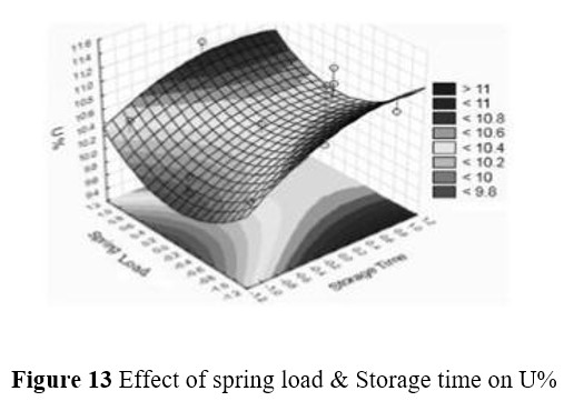
The yarn samples made from low spring load sliver can springs and at high storage time gives higher value of unevenness. Reason being, at high storage time chances of fibre leaking from adjacent sliver coils are high. Uneven sliver results in uneven yarn after material being drafted over speed frame and ring frame. It should be shown by the following graph.
6.5 EFFECT OF SPRING LOAD AND COIL POSITION ON STRENGTH CV%
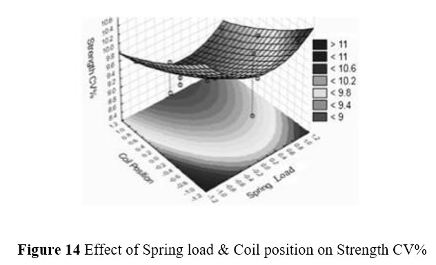
Bottom sliver coils from reduced spring stiffness of older sliver can gives higher strength CV%. During sliver deposition in reduced stiffness sliver can spring, after deposition of few sliver layers, most of free height gets compressed and length of sliver in hanging zone between coiler and top sliver layer will be more, sliver stretching may occur in this zone because of its own weight of sliver. Hence, long thin places may be introduced in final yarn and also influence strength of single combed yarn. Bottom sliver coils from low spring load sliver cans gives high strength CV% is shown in the following graph.
6.6 EFFECT OF STORAGE TIME AND COIL POSITION ON STRENGTH CV%
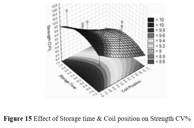
It has been observed that high storage time have an adverse effect on yarn quality. Strength CV% is high at higher storage time and effect is more prominent in case of bottom sliver position. At high storage time bottom sliver coils stick with adjacent coils because these coils gets sandwiched between top sliver coils weight and force applied by spring through top plate. During withdrawal fibre leaking from one layer to another may occur and result in long thing places and high strength CV% in final yarn manufactured from this uneven feed sliver.
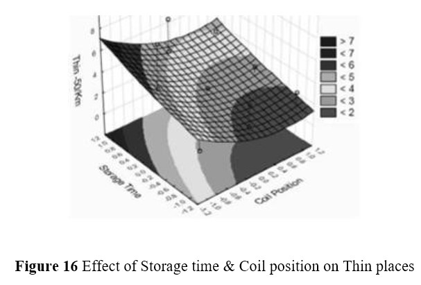
6.7 EFFECT OF STORAGE TIME AND COIL POSOTION ON THIN PLACES
It has been found that at high storage time, bottom position sliver coils will stick with one another because of low inter fibre friction and more contact area of flattened sliver coils. Sliver splitting and stretching at speed-frame will be more in case of high storage time and its effect will be more prominent in case of bottom coils. Number of thin places in yarn will be more if we allow high storage time to finished combed sliver.
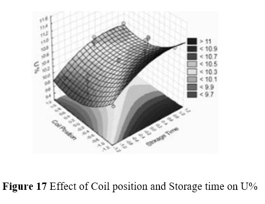
6.8 EFFECT OF COIL POSITION AND STORAGE TIME ON U%
U% of yarn have been found increasing with increase in storage time of a can sliver. At higher storage time, bottom sliver coils may experience compression forces applied by top coils sliver layer and reverse spring forces for longer period. As a result of this, sliver flattening of bottom sliver will take place and sliver stretching would occur at while withdrawing sliver at speed-frame, cause higher U% in yarn.
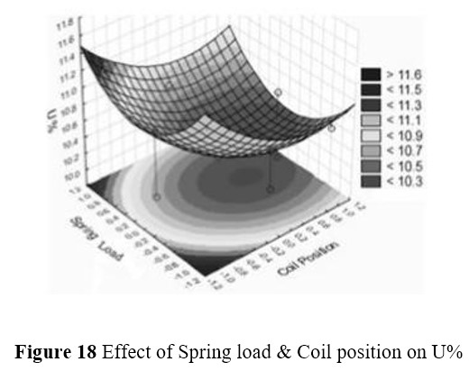
6.9 EFFECT OF SPRING LOAD AND COIL POSITION ON U%
Bottom coils stick with subsequent sliver layers, combined effect of low spring load for bottom coils result in higher U% in yarn. As discussed earlier, the main reason is disturbed structure of bottom sliver coils and then sliver stretching at creel zone of speed-frame.
CHAPTER 7
CONCLUSION
From this report, I have conclude that the effect of coil position and storage time is found significant whereas the effect of spring load is not that much significant on yarn unevenness. Spring load, coil position and storage time has been found significantly influencing thin places -50%/km. Only disturbed bottom sliver coil position is found influencing strength CV% of yarn. Effect of middle, top sliver coils, spring load and storage time on strength CV% is non-significant. Sliver cans springs having low spring stiffness were found significantly influencing yarn quality because sliver stretching during deposition at finisher draw frame sliver can and withdrawal of sliver from storage cans at speed frame. Combed slivers are very sensitive to stretching. So for avoiding the false draft in the creel we have use UCC can which is manufactured by Rimtex. It is also economically cost effective and less occupation of floor space in the spinning mill.
REFERENCES
- Klein W., “The Rieter Manual of Spinning, Vol.3”, Rieter Machine Works Ltd., Winterthur, 2014.
- Lord P.R., “Yarn Production: Science, Technology and Economics”, The Textile Institute, Manchester, 1999.
- Yarn manufacture I – “Principle of carding and drawing” – NPTEL, IIT Delhi.
- Sukhvir Singha & N. Bhowmick, Influence of sliver can spring load, coil position and storage time on yarn quality, International Journal of Fiber and Textile Research (2014), 4(4) : 83-86.
- Ravichandran N, Mariappan S, Shanmuganandam D, A study on materials handling in spinning mills Indian Textile Journal. (2008), 118, 31.
- Sinha S K, Arora V, Sliver Cans -An Influencing Factor of Yarn Quality, Textile Trends, (1998), 41, 27.
(732)
