Measuring Devices in Carding | Part 05

Md. Omar Faruk
Latest posts by Md. Omar Faruk (see all)
- Operation Management | Supply Chain Management - April 15, 2020
- Thread Numbering System - September 5, 2018
- Viscose Fiber | Viscose Rayon Production | Properties of Viscose Rayon - July 5, 2018
Part 01 | Carding Introduction | | Part 02 | Carding Action
Part 03 |Card Clothing | Types of card clothing | | Part 04 | Auto Leveling in Carding
Part 05 | Measuring Devices in Carding | | Part 06 | Characteristics of Card Sliver
Measuring Devices in Carding
Carding: Carding is a mechanical process that disentangles, cleans and intermix fibers s to produce a continuous web or sliver suitable for subsequent processing. In this process fibers are opened, parallelized & removes dust, impurities, short fibers to produce continuous strand of sliver. This is achieved by passing the fibers between differentially moving surfaces covered with card clothing. The word is derived from the Latin “CARDUUS” meaning thistle or teasel, as dried vegetable teasels were first used to comb the raw wool.
Measuring Devices in Carding:
1 . Active Pneumatic System:
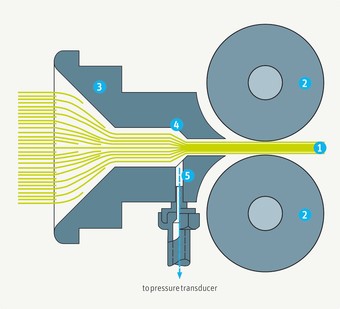
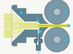
In a normal card, a funnel is provided before the calendar rollers (2) in order to collect the web into a sliver. In Zellweger equipment, this funnel is developed to form a measuring device based on a simple physical principle. When fiber material enters the funnel (3), it carries along quite an amount of air held between the fibers. Owing to the continuous convergence of the funnel, air is squeezed out as the material passes through.
This generates air pressure in excess of atmospheric pressure, which is a function of the sliver cross-section if the sliver speed is kept constant. If all fiber characteristics also remain constant, this pressure is proportional to the volume. A lateral bore (5) in the funnel, and corresponding leads, transmit the pressure into the chamber of a pneumatic-electrical pressure transducer, using electrical induction to convert the pressure into an electrical signal.
Comparison of the signal with a set value enables pulses to be generated to control the electronic units in the regulator equipment. The advantage of active pneumatic measurement lies in the simplicity of the system, which does not require additional and/or sensitive moving parts. The disadvantage is that measurement is affected by the fiber count and hence count variation can lead to errors.
Fig: Active Pneumatic system
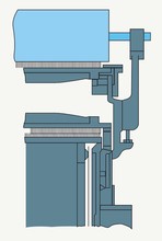
2 . Mechanical Measuring System:
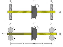
This is the most common system for deriving a measured value. Usually, two material-forwarding rollers are used. One of these rollers must be movable (up and down) relative to the other. The relative movement, corresponding to the volume of the material passing through (a) gives the instantaneous value required for the regulation operation.
The rollers can be smooth or grooved, b and c. The latter arrangement prevents lateral escape of the fibers and thus gives more precise measurement. However, it must be so designed and must operate in such a manner that the fibers are not crushed at the roller edges.
The advantage of the mechanical principle lies in its insensitivity to variations in the characteristics of the raw material, with the possible exception of bulk.
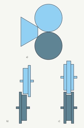
Fig: Mechanical measuring system
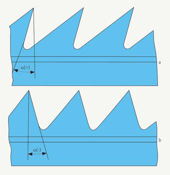
Carding angle: This is the most important angle of the tooth; the aggressiveness of the clothing, the hold of the fibers, is determined by this parameter. The angle specifies the inclination of the leading face of the tooth to a vertical. It is described as positive, negative or neutral. The angle is neutral if the leading edge of the tooth lies in vertical (0⁰). Clothing with negative angles is used only in taker-in, in processing of some synthetic fibers. Since the fibers are held less strongly by this form of tooth, they are transferred more easily to the cylinder and the clothing are less inclined to choke. Carding angles normally fall into following ranges:
Taker-in +5⁰ to -10⁰ (-15⁰)
Cylinder +12⁰ to +27⁰
Doffer +20⁰ to +40⁰
Striping:
When the wire points of two closed surface are inclined to the opposite direction and both the surface rotate to the opposite direction then the action is called stripping direction. Stripping action occurs between taker-in and cylinder.
Methods of stripping:
- Roller stripping
- Dustless stripper
- Vacuum stripper
- Air stripper
- Continuous stripper
- Static stripper
1 . Roller stripping: Conventional method of stripping. A wooden roller of about 6” diameter and equal length to the card width, covered with a special stripping wire fillet is put against the cylinder by opening the front door. The stripping is done by passing the point of stripping roller to the cylinder wire by point to back action and with higher surface speed for the stripping roller.
2 . Dustless stripper: this method consists of plain roll, partially enclosed by sheet metal hood from which a large flexible tube leads to a special stripping truck. A small suction fan fitted on the truck exhausts into a fabric bag. It works exactly like roller stripping but brass normally is kept running during stripping. As a result, dust which would normally be thrown into the air is drawn away by the suction and collected in the dust bag.
3 . Air stripper: In this method truck is completely eliminated by one small stripping brush covered with special stripper clothing placed just above the junction of the doffer and cylinder. The roller is driven by main cylinder pulley through binder pulley.
4 . Vacuum stripper: No stripping roller is used. This system requires special air pump to maintain a high vacuum and large waste receiving drum where the waste is collected. Nozzle is used to collect waste from the surface of the cylinder or doffer etc.
5 . Continuous stripping: This is also nozzle and suction type stripping. It is automatic continuous stripping device. Its several advantages are given below:
- Reduction waste and saving in cotton.
- Reduction in labor cost required for stripping.
- More machine utilization and more production.
- More savings in power.
- More fillet life
Grinding: Grinding is the operation by which the good working condition of the wire points of all organs in the carding machine is maintained.
Intervals between grinding
The operating life of clothing is quoted in terms of the total throughput of material. For the cylinder it normally lies between 300,000 and 600,000 kg, but it can be higher in some circumstances.
The deterioration in quality from one grinding interval to the next arises from the fact that the teeth are ground down to successively lower heights, the lands at the teeth points become steadily larger, and softer metal layers are gradually exposed. The following grinding intervals are currently in use:
|
Cylinder |
Flats |
|
|
First grinding after [kg] |
80,000 – 150,000 |
80,000 – 150,000 |
|
Each additional grinding after [kg] |
80,000 – 120,000 |
80,000 – 120,000 |
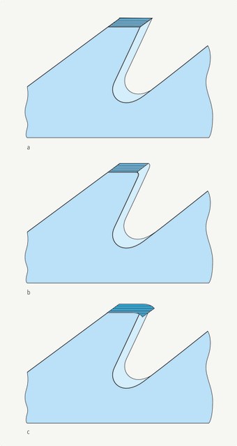
Grinding Depth:
Grinding is carried out with the cylinder rotating in its normal direction at normal speed, so that the grinding roller moves with (not against) the teeth of the clothing. The grinding depth is such that a plane surface with a sharp edge is produced at the point of the tooth (a). Satisfactory carding will not be achieved if too little material is ground away so that the front edge stays rounded (b), or if the grinding operation is too harsh (too much pressure on the grinding roller) so that a burr is formed at the tooth edge (c).
Methods of grinding:
- Traverse wheel grinding
- The dead roller or full width grinding roller.
Traverse wheel grinding:
In this method there is an emery roller of 3.5” width which moves from one side to another by traversing motion.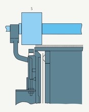
Advantages:
- Better grinding action.
- No risk of hooking or fusing of wires.
The dead roller or full width roller:
Here rotate covering the full width of the card. Roller is covered with emery fillet.
Advantage:
- Long grinding roller is used in case of high speed grinding.
- It is used to produce low and medium count yarn
Part 01 | Carding Introduction | | Part 02 | Carding Action
Part 03 |Card Clothing | Types of card clothing | | Part 04 | Auto Leveling in Carding
Part 05 | Measuring Devices in Carding | | Part 06 | Characteristics of Card Sliver
(1705)
Md. Omar Faruk
Latest posts by Md. Omar Faruk (see all)
- Operation Management | Supply Chain Management - April 15, 2020
- Thread Numbering System - September 5, 2018
- Viscose Fiber | Viscose Rayon Production | Properties of Viscose Rayon - July 5, 2018